The MAX7219 simplifies driving LED displays, making it ideal for applications such as scoreboards, clocks, and scrolling text displays. Its compact design and ease of use make it a favourite among hobbyists and electronics enthusiasts.
Features:
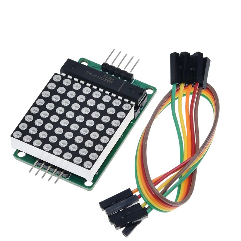
Integrated Serial Input/Output Common-Cathode Display Driver:
The MAX7219 is designed to interface microprocessors (μPs) with 7-segment numeric LED displays, bar-graph displays, or individual LEDs.
BCD Code-B Decoder:
On-chip BCD code-B decoder for efficient data handling.
Multiplex Scan Circuitry:
Enables multi-channel scanning and word drive.
8x8 Static RAM:
Stores data for each digit.
Segment Current Control:
Only one external register needed to set the segment current for all LEDs.
Serial Interface:
Convenient four-wire serial interface compatible with most general-purpose microprocessors.
Coding Options:
Allows the user to select coding or non-coding for each data.
Low-Power Shutdown Mode:
Contains a 150μA low-power shutdown mode.
Brightness Control:
Analog and digital brightness control.
Scan-Limit Register:
Allows displaying from 1 to 8 digits.
LED Light Detection Mode:
Provides an option to light up all LEDs.
Module Parameters:
Common Cathode Lattice:
A single module can drive an 8x8 common cathode lattice.
Operating Voltage:
Module operates at 5V.
Module Size:
Dimensions: 5cm (length) x 3.2cm (width) x 1.5cm (height).
Mounting Holes:
Four screw holes with a 3mm aperture for secure installation.
Cascading Support:
Input and output interfaces allow multiple modules to be cascaded.
Wiring Instructions:
Connect the module’s input port (left side) and output port (right side).
For controlling a single module:
Connect the input port directly to the CPU.
For cascading multiple modules:
Input termination module connects to the CPU.
Output termination module connects to the input of the next module.
Repeat this pattern for additional modules.
Example for an MCU (e.g., Arduino UNO):
VCC: Connect to 5V
GND: Connect to GND
DIN: Connect to P22
CS: Connect to P21
CLK: Connect to P20
-
Part No
LEDMX-887219
-
Manufacturer
-
Stock No
1815-EA1
-
SKU No
274628
*Prices subject to change without notice. We reserve the right to limit quantities.
To purchase bulk quantities, Please contact our Sales Department
(+1-416-494-8999) or email shop@sayal.com
Documents & media will load when this tab is opened...